
Arc Magnets for Stator: Fitment Checker & Guide
Arc magnets for stator assemblies sit inside the stationary housing in the PMDC arrangement shown here. Confirm magnet location, then estimate radial space from radii, air gap and assembly allowances.
Reviewed 2026-09-21 · Preliminary geometry only · Method & limits
Evaluation Results
1. Decide location, space and validation separately
| Decision | Evidence / method | Action |
|---|---|---|
| Use the stationary-housing model only for the shown PMDC arrangement. | Oriental Motor: Brushed DC Motor Structure and Principles | Confirm which part rotates before measuring. |
| Available radial space is smaller than housing radius minus rotor radius. | Radial stack equation below | Subtract air gap, adhesive and an explicit reserve. |
| Temperature capability depends on grade and operating point. | Arnold: 3 Key Parameters When Choosing a Permanent Magnet | Request grade curves at the intended hot and cold conditions. |
| A positive geometry result is insufficient for release. | Arnold: Magnetization Losses in Rare Earth Permanent Magnets (PDF) | Validate magnetic loading, bonding and assembly tolerances. |
2. Where are the magnets in your motor?
Permanent-magnet brushed DC motors can place field magnets around the rotating armature. The tool covers concentric arcs inside that stationary housing. Brushed wound-field motors, coreless arrangements with a different radial stack and specialized stator-PM machines need their own section drawing.
| Arrangement | Magnet location | Use this calculation? |
|---|---|---|
| PMDC, outer stationary field magnets | Inside stationary housing; wound rotor inside | Yes, when the drawing matches the radial stack. |
| Typical BLDC inrunner | Inner rotating rotor; wound outer stator | No — review rotor dimensions and retention. |
| Typical BLDC outrunner | Rotating outer shell; wound inner stator | No — the outer shell is not a stationary stator housing. |
| Other / unknown | Not established from the keyword alone | No — identify the motor and magnet location first. |
Sources: Oriental Motor: Brushed DC Motor Structure and Principles; Portescap: Eliminate Design Compromises in Industrial Power Tools. For adjacent geometry, see arc magnets for motors.
3. Reproduce the radial envelope calculation
t = Rh − Rr − g − b − s
Minimum finished magnet inner radius = Rr + g + s
Maximum finished magnet outer radius = Rh − b
Rh: housing bore radius; Rr: rotor outer radius; g: target running air gap; b: cured radial bond line; s: additional radial reserve. All values are in mm.
This equation is our geometric derivation of the displayed stack. It is not a motor-design standard. Use finished, coated dimensions and a consistent reference temperature. The tool assigns the reserve to the inner clearance budget and rejects zero or negative remaining thickness.
The calculation accepts up to three decimal places and uses integer micrometres internally. The 10,000 mm input ceiling is a software bound, not a manufacturing capability. There is no calculation of arc angle, axial length, pole coverage, torque or magnetic flux.
4. Build a clearance budget before choosing thickness
A smaller air gap can improve magnetic coupling, but requires tighter control of the mechanical stack. Portescap: Electric Motor Efficiency explains this tradeoff; it does not specify a universal air gap for all PMDC motors. The tool defaults are worked-example assumptions.
| Item | Known here | How to establish it |
|---|---|---|
| Running air gap | User entry only; actual requirement unknown | Check running clearance over speed, load and temperature. |
| Cured bond line | User entry only; adhesive process unknown | Use the chosen adhesive data sheet and a validated assembly process. |
| Radial reserve | A single user-entered budget | Account for runout, bearing play, concentricity, coating, thermal growth and dimensional tolerances. |
| Worst-case dimensions | Not inferred from nominal radii | Use a minimum bore and maximum rotor radius, or include their deviations in reserve. Avoid counting the same variation twice. |
Do not reduce a required air gap just to obtain a positive result. Review the housing envelope, rotor size or magnet design with the motor engineer.
5. Compare materials without treating a grade as a motor rating
| Material | Reason to consider | Tradeoff / validation |
|---|---|---|
| Ferrite / ceramic | Cost-sensitive stationary field designs | Lower magnetic output can require more space; evaluate hot output and cold demagnetization behavior. |
| NdFeB | Compact designs needing high magnetic output | Check the temperature-dependent demagnetization curve and corrosion protection. |
| SmCo | Temperature stability is a priority | Compare magnetic performance over duty, handling constraints and a drawing-specific quotation. |
Sources: Arnold: 3 Key Parameters When Choosing a Permanent Magnet; Eclipse Magnetics: Ferrite (Ceramic) Magnet Material. These are screening directions, not interchangeable material specifications. A maximum temperature, grade suffix or room-temperature strength alone cannot qualify the assembled motor. Current prices and lead times require supplier confirmation.
6. Qualify the joint and the assembly process
Specify cured bond thickness, substrate and coating compatibility, surface preparation, cure conditions and retention tests. Henkel: Motor Magnet Bonding and Manufacturing Tolerances documents one rotor-bonding product and its treatment of manufacturing gaps. That example does not prescribe a stator adhesive or a universal 0.05–0.25 mm bond line.
For this stator design, request adhesive data for the actual surfaces, temperature cycling, fluids and vibration. If clips or other retainers are used, include their occupied space in the drawing review. The calculator reserves radial space only; it does not calculate joint strength or life.
7. Control magnetic, assembly and cost risks
A magnet may undergo irreversible loss when its local operating point crosses the knee of its demagnetization curve. Comparing one reverse-field value with Hcj alone is insufficient. Evaluate the actual grade at temperature and under the motor's peak-current duty. Source: Arnold: Magnetization Losses in Rare Earth Permanent Magnets (PDF).
| Risk | What the tool misses | Minimum next action |
|---|---|---|
| Misuse / wrong topology | Whether the measured shell rotates | Confirm section drawing and polarity map before ordering arcs. |
| Rubbing or loose magnets | Worst-case tolerances and bond strength | Review the complete clearance stack and test retained assemblies. |
| Demagnetization or thermal mismatch | Temperature-dependent magnetic load line | Assess hot and cold grade curves under peak current; use electromagnetic analysis and motor tests. |
| Cost escalation | Tooling, yield, coating, fixtures and inspection | Quote the same finished drawing and inspection scope across suppliers. |
The review actions are engineering recommendations derived from the stated limitations. More radial space does not establish that a thicker magnet improves the full motor design.
8. Three reproducible screening examples
Illustrative inputs only; these are not tested motors or recommended clearances. PMDC examples use Rr = 20, g = 0.5, b = 0.1 and s = 0.2 mm.
| Scenario | Process | Result / next action |
|---|---|---|
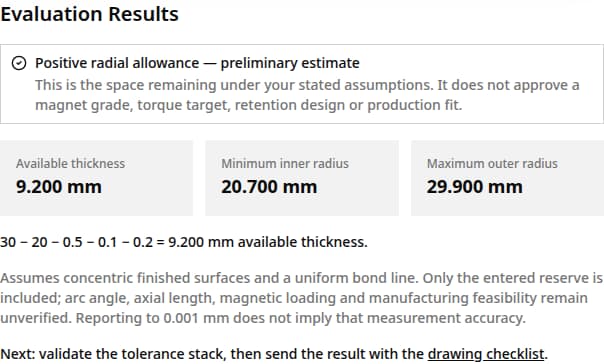
| PMDC; Rh = 30 mm | 30 − 20 − 0.5 − 0.1 − 0.2 | 9.200 mm available; inner radius ≥20.700 mm, outer radius ≤29.900 mm. Validate the drawing. |
| PMDC; Rh = 20.8 mm | 20.8 − 20 − 0.5 − 0.1 − 0.2 | 0 mm remains; rejected. Revisit the envelope and tolerance budget. |
| BLDC outrunner | Topology gate precedes dimension arithmetic | No stator dimensions returned. Inspect the rotating shell and use a rotor-specific design review. |
View the calculator example: 9.200 mm available
9. Turn the result into a drawing review
Copy the result brief and provide the items below through the contact page. If the geometry is unknown or rejected, send a labeled section drawing first.
- Motor topology; which part rotates; drawing revision and units.
- Finished inner/outer radii, mechanical arc angle, axial length, edge details and dimensional tolerances.
- Poles per motor, pieces per pole, magnetization direction and a polarity map tied to the working surface.
- Candidate material/grade, required magnetic acceptance limits, coating and operating temperature range.
- Peak current and duty, speed, vibration, environmental exposure, adhesive and retention method.
- Prototype and production quantities, inspection requirements and delivery location.
Mechanical arc angle is a geometric dimension. Electrical angle also depends on pole-pair count; this tool calculates neither. No supply capability, fit or lead time is confirmed by a result.
Send drawing for review10. Questions before specifying stator arcs
Topology and measurement
Do brushless motors use stator magnets?
Typical inrunner and outrunner BLDC motors place the magnets on the rotor. Specialized machines can differ; use the section drawing rather than the name alone. See the topology comparison and its manufacturer sources above.
Does every brushed motor fit this tool?
No. Select PMDC only for field arcs inside a stationary housing around the rotating armature. Wound-field motors and other radial arrangements require a separate model.
Can I enter diameters?
Divide both housing bore diameter and rotor outer diameter by two first. Air gap, bond line and reserve are radial values already.
Can the tool identify a replacement magnet?
No. An existing motor also needs part identification, polarity, grade, arc angle, axial length, tolerances and retention details. A radial envelope alone does not identify a replacement.
Result and boundaries
Is 9.200 mm a recommended magnet thickness?
No. It is the space remaining in the example after subtracting the entered allowances. Electromagnetic design and manufacturing constraints may require a different thickness.
Are the default air gap and bond line standard values?
No. Every default is an illustrative input. Establish project values from the motor drawing, tolerance stack and selected adhesive process.
Why was a zero-thickness result rejected?
The entered housing provides no remaining radial space for a magnet after clearance and assembly allowances. Check radius-versus-diameter units and revise the design envelope.
What does a zero reserve mean?
No extra radial allowance is included beyond the target gap and bond line. This is a sensitivity case unless the drawing already accounts for all relevant variation.
Material and assembly
Can I replace ferrite with NdFeB of the same size?
Not on geometry alone. Magnetic loading, commutation, temperature, corrosion and retention need review. Use the material comparison as a screening guide.
Does a temperature rating guarantee no demagnetization?
No. Review the actual grade curves at the operating temperatures, geometry and reverse-field load. The assembled motor also has adhesive, winding and mechanical limits.
How should I specify magnetization direction?
Provide an approved magnetization vector and polarity map on the drawing. The arc shape alone does not define them; this tool does not predict the resulting field.
What should I send when the result is unavailable?
Send a section drawing showing which part rotates, dimensions and units, then the required duty and quantity. The drawing checklist above is the minimum practical next step.
11. Sources, review date and evidence limits
Published 2026-09-21 · Reviewed on 2026-09-21. Published by Magatom Dynamics Co., Ltd.. Manufacturer references support the stated principles, not approval of your motor. Publication dates and scope limits appear below. The radial equations and examples are this page's own geometry, not measured performance data.
- Oriental Motor: Brushed DC Motor Structure and Principles
PMDC stator field and rotating windings; updated October 29, 2021. Does not establish dimensions for a particular motor.
- Portescap: Eliminate Design Compromises in Industrial Power Tools
Inrunner and outrunner magnet locations; web publication February 2022. Specific motor configurations, not every possible topology.
- Portescap: Electric Motor Efficiency
Air gap and manufacturing tolerance tradeoff; undated. No universal PMDC air-gap range is specified.
- Arnold: 3 Key Parameters When Choosing a Permanent Magnet
Material, temperature and cost tradeoffs; June 28, 2016. Material guidance, not a finished motor temperature rating or current quotation.
- Eclipse Magnetics: Ferrite (Ceramic) Magnet Material
Undated material guide; reviewed September 21, 2026. Supports checking ferrite coercivity in the cold. Any demagnetization threshold depends on magnet shape and application.
- Henkel: Motor Magnet Bonding and Manufacturing Tolerances
Product-specific rotor bonding example; April 20, 2020. Supports accounting for bond gaps, not a stator adhesive recommendation or universal bond-line thickness.
- Arnold: Magnetization Losses in Rare Earth Permanent Magnets (PDF)
Rare-earth demagnetization curves, external fields and temperature; June 2022. Application-specific load-line analysis is still needed.
Unknown until confirmed: finished-motor temperature rating, allowable air gap, adhesive thickness, grade suitability, price and lead time. No public source here establishes universal values for those inputs.
Prepare your stator magnet specification
Bring the radial envelope, section drawing and operating duty to a drawing review. The checklist above identifies the dimensions and evidence still needed.
Request a stator drawing review